How to design an Airplane Wing - Aspect Ratio, Taper Ratio, Sweep, Twist, Incidence, Dihedral
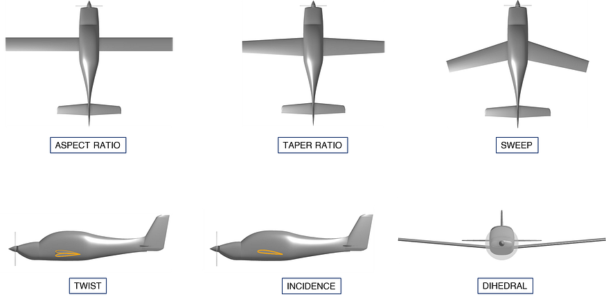
In this post, we will look at all the important parameters used to decide on the wing geometry and layout while designing an aircraft. The parameters discussed are aspect ratio, taper ratio, sweep, twist, incidence, and dihedral, all of which are crucial for wing design. Let’s get started.
You can also watch this video for more on wing design:
Once the total weight of the airplane is estimated, we can calculate the wing area by simply dividing the total weight by the chosen wing loading value. The wing loading value may be selected based on the stall speed requirements or by looking at the wing loading values of similar designs and choosing an appropriate one. If you haven’t selected it yet, you can watch one of my previous videos on wing loading for more info.

Now, we create a reference wing by selecting various geometrical parameters. This reference wing is different from the actual wing in two ways. First, it extends through the fuselage to the centerline and its tip is squared even if the actual wing may have rounded wingtips. Second, the root airfoil of the reference wing is considered at the ceterline and not at the wing fuselage attachment. But this is only for aerodynamic purposes as it is not built.

To create this reference wing, we need to select the aspect ratio.
The effect of aspect ratio can be seen in birds. Those with long and narrow wings can glide easily, on the other hand, those with short and thick wings have greater manoeuvrability, but they must work harder to stay in the air.

When we select an Aspect Ratio for a wing, we are actually selecting its wingspan, as the wing area is already found. Wingspan is the main factor in determining drag due to lift. In general, long and skinny wings have less drag for a given lift as compared to short and fat wings. In other words, the longer the span, lesser the drag due to lift.
But increasing the wingspan also increases the weight and bending moments, so a compromise must be made. Also, a long wingspan is constrained by hangar and storage requirements.
Lower aspect ratio wings stall at a higher angle of attack as compared to a higher aspect ratio wing.
For initial design, the aspect ratio can be selected based on historical data. For example, if we are designing a trainer type aircraft, we can look at a bunch of similar aircraft and see what aspect ratio values they use, and pick an appropriate one. After drawing the aircraft, an aspect ratio trade study can be performed to optimize its value.
Taper Ratio.
It is the ratio of the tip chord to the root chord of the wing. As mentioned earlier, the root chord is considered at the fuselage centerline.

Tapering is done to change the spanwise lift distribution on the wing. Spanwise lift distribution simply means how much lift occurs at what spanwise location. If done properly, tapering can reduce drag. A wing with no taper has too much lift at the wingtips, which is bad in terms of drag due to lift. Ideally, we want the lift distribution to be elliptical, because this gives the minimum drag due to lift value. For an untwisted and unswept wing, this occurs when the wing itself is shaped like an ellipse. This design can be seen on the famous spitfire aircraft.
A taper ratio of 0.45 is almost as good as an elliptical wing and is relatively easier to make. Taper also reduces weight as the root chord is longer and thus is better suited to handle the bending moments.


If the taper ratio is too high, meaning that the tip chord is too small, there could be a problem of tip stall. In this regard, the untapered wing has an advantage. It tends to stall starting at the root which makes the airplane more controllable in a stall. This is because the ailerons at the tips will still be in use giving the pilot manoeuvrability. Ideally, the taper ratio should be selected based on the drag, stalling pattern, weight, and complexity of manufacturing, which again shows a compromise between various factors in aircraft design.
Sweep.
Sweeping the wing is more aesthetically pleasing, but sweep decreases the lift produced by the wing by the cosine of the sweep angle. For example, a 60 degree sweep will cause the wing to lose half of its lift. It also increases the structural weight and makes the ailerons and flaps work poorly. Swept wings are also more prone to flutter issues.
Swept wings have aerodynamic advantages when it comes to flying at high speeds. Sweeping the wing increases the speed at which shocks first form. A swept wing also has a stabilizing effect like the dihedral of a wing.
There are 2 important sweep angles. The leading edge sweep is important for supersonic flight. In order to reduce drag, the wing is commonly swept in such a way that the leading edge is behind the mach cone. This is not always true, as too large a sweep is impractical from a structural standpoint.
The second sweep angle is that which is measured with reference to the quarter chord line. This sweep angle is mostly related to subsonic flight.

Forward sweep can also be used to get the aerodynamic benefits at high speeds, but in this case, there is a problem of divergence. Divergence can cause the wing to twist uncontrollably and even break off.
Mean Aerodynamic Chord.
Now, we can decide on where to place the wing on the fuselage so that the airplane is stable. We need to design the airplane so that the center of gravity and the wing are in the right location with respect to each other. To do this, we first need to find out the Mean Aerodynamic chord or MAC of the wing. The MAC is some chord c, at a distance Y from the centerline. It acts as if all the wing’s area is concentrated on that chord. The entire wing will have its aerodynamic center at the quarter chord point of the Mac. The specialty about this point is that if the total pitching moment is measured from that location, it does not change when the angle of attack changes. For more on how to find the MAC of a wing, see the wing design video mentioned earlier.

This point is critical in aircraft design for stability. If the airplane had neither fuselage nor tails, and the CG was located exactly at this point, the airplane would be neutrally stable. Adding tails increases the stability.
A stability analysis is required to estimate the correct placement of the wing and CG. For initial design and tests, the CG can be placed at the quarter chord point of the MAC.
Twist.
Twist is used to prevent tip stall and to improve the lift distribution on the wing. Twist changes the spanwise lift distribution because it changes the local angle of attack seen by each airfoil. This influences the drag due to lift.
Typically, wings are twisted between 0 and minus 5 degrees, the minus sign indicating that the leading edge is twisted downwards.
Geometric twist is the actual change in the airfoil angle of incidence, measured with respect to the root airfoil. In most cases, the tip airfoil is at a negative angle of attack compared to the root airfoil. This is called a washout. A wing with washout tends to stall at the root before the tip, which improves control.

Aerodynamic twist is defined as the angle between the zero lift angle of an airfoil with respect to the zero lift angle of the root airfoil. If identical airfoils are used, then aerodynamic twist is equal to the geometric twist. On the other hand, a wing with no geometric twist can have aerodynamic twist if, for example, the root airfoil is cambered, but the tip airfoil is symmetric.

Wing incidence.
It is the pitch angle of the wing with respect to the fuselage. If the wing is untwisted, the incidence angle is between the fuselage axis and the airfoil’s chordlines. If the wing is twisted, then wing incidence is usually measured with respect to the Mac or the root of the exposed wing. Aircraft drawings or design data frequently provide the values for the incidence of the root and tip, which defines the twist.

Wing incidence is chosen to minimize drag during cruise. This is done such that when the wing is at the correct angle of attack for the desired lift, the fuselage is at an angle of attack for minimum drag. For typical fuselages, this is angle is often a few degrees nose up as the fuselage also contributes to lift.
A simplified version of wing theory can be used to estimate the wing incidence angle. For this, the cruise lift coefficient is needed, which can be found using this formula. Depending on whether the wing is unswept or swept, the formulae shown here can be used to estimate the wing incidence angle. The term alpha zero lift comes from the airfoil data. It should be noted that the incidence angle calculated here is the angle at the Mac. So, we need to layout the wing such that we have the desired angle of incidence at the Mac, and the twist begins at the Mac, increasing inwards towards the root airfoil and decreasing outwards towards the tip airfoil.

Dihedral.
It is the angle of the wing with respect to the horizontal, when viewed from the front. When an aircraft is rolls to one side, a positive dihedral angle tends to roll it back to level. Wing position also has an effect on the effective dihedral. That is why many high wing transport aircraft actually need a negative dihedral, called anhedral, to counter excessive effect of dihedral. Excessive dihedral can be bad because it can cause stability issues like the dutch roll.

Generally, low wing aircraft require more dihedral than high wing aircraft due to the positioning of the wing. A high wing has an increased dihedral effect and therefore needs a smaller geometric dihedral.
A simple explanation as to why this happens is shown here. When rolled to one side, an aircraft will sideslip down to that side. During this sideslip, the fuselage pushes the air over and under itself.

In case of a high wing airplane, the air moving over the top of the fuselage moves in such a way that the windward wing sees a higher angle of attack near the root, and the leeward wing a lower angle of attack. This causes a rolling moment that stabilizes the aircraft.


The opposite is true for a low wing aircraft. This is why low wing airplanes need more dihedral, and high wing planes like Cessna 172 require almost none.

These were the important parameters we need to define while designing a wing. If you found this helpful, support me via my BuyMeACoffee page: https://buymeacoffee.com/aircraftdesigntoolbox
Thank you for your support!


Comments
Post a Comment